
PRODUCT RANGE
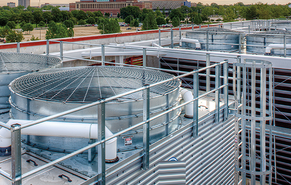
COOLING TOWER SYSTEM
A cooling tower extracts heat out of process cooling water and pushes it into another medium, usually air so that the process cooling water is cooled and ready to be recirculated.
Supply, Service of Cooling Tower, Package Towers, Spares Supply & Maintenance.
1. Evaporative Cooling Tower Installation
TPCO offers turnkey installation of various types and models of cooling towers, which will be designed by the manufacturers and installed to suit your exact requirements. We have access to various cooling tower OEM’s, enabling us to supply a full-service package ranging from design and engineering to project management. This ensures premium quality, technical expertise, safe working practices, and a cost-effective and faultless supply chain. Our Supply and installation services cover the following types of cooling towers:
- Counter Flow Cooling towers
- Cross Flow Cooling towers
- Closed Circuit Cooling Tower
- Air Cooled Steam Condenser
- Air Cooled Heat ExchangerFin Fan Coolers
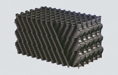
Fills are used in various applications and primarily allow to increase the exchange surface, with equal volume occupied.
Fill consists of thermoformed corrugated sheets made of rigid polyvinyl chloride (PVC), impervious to decay, fungus, and biological attack. The sheets are bonded to form modules that can be dimensioned to fit any application.
Our Film fill combines properties related to a media’s ability to allow the substance to migrate through it while maintaining thermal efficiency _ this then allows for the use of film fill where fouling risks occur.
Mainly used to separate drops of water present in the air stream, both for vertical flows (modular panel separators) than for horizontal flow (separators made of PVC profiles)
To ensure their efficiency they have to be erected conforming to our guidelines and carefully maintained.
We offer:
- We type (with different pitches)
- Cellular type
- Panel separator

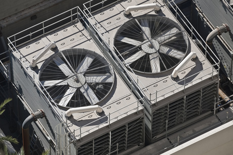
Fans may be classified as centrifugal fans or axial – flow fans. in centrifugal fans, the air is led through an inlet pipe to the centre or eye of the impeller, which forces it radially outward into the volute or spiral casing from which it flows to a discharge pipe. In an axial- flow fan, with the runner & guide vanes in a cylindrical housing, air passes through the runner without changing its distance from the axis of rotation.
There would be no centrifugal effect on the airflow generated. Guide or stator vanes serve to smoothen/straighten the airflow and improve efficiency. In general, an axial flow fan is suitable for a larger flow rate with a relatively small pressure gain and a centrifugal fan for comparatively smaller flow rate and large pressure rise.
YASHAS Fans are manufacturing by a unique proprietary (under patent) that allows for the manufacturing & construction of single piece hollow or solid fan blades which can achieve higher efficiency.
6 ft. to 16 ft. Designated Medium fan from 4 blade to 10 blade models with FRP seal disk. 17 ft. to 36 ft. Designated Senior fan from 4 blade to 12 blade models with FRP seal disk Fan Duties range:
No. of Blades As above (4 TO 10 BLADES *4 TO 12 BLADES) Airflow Up to 900 m3/sec
Static pressure standard fan design up to 325 pa Speed: Tip Speed up to 76.2 M/sec Power Rating For standard blade model up to – 360 KW
Operating Temp20 Deg.C to +120 Deg.C
Our fan Blade Aerofoil is the one of the Aerofoil designed Licensed from USA
Fan adopting this aerofoil has been tested by national Renewable Energy Laboratory (NREL) Operated for the U.S Department of Energy. Tests found 7 to 12 % better total efficiency in comparison to one of the world leading fan supplier
Blades are painted with special PU paint which is tested for 100 hrs salt water test and suitable for acidi conditions & protection against UV. Special silver colour metal filled PU paint on leading edge for protection against erosion.
The FRP fans offer certain critical advantages over conventional Fan
Optimal aerodynamic design of an impellers to provide higher efficiency for any specific application.
Reduction in overall weight of the fan, thereby extending the life of mechanical drive systems
Requires lower drive motor rating and light duty bearing system.
Low power consumption resulting in appreciable energy savings
FRP fans fabricated by compression moulding/ resin transfer moulding technique would have uniform dimensions and consistent quality.
Lower flow noise and mechanical noise levels compared to the conventional metallic fans.
Longer life of fans due to improved mechanical strength
Operating Ranges Fan Diameter range:6 ft. to 16 ft. Designated Medium fan from 4 blade to 10 blade models with FRP seal disk. 17 ft. to 36 ft. Designated Senior fan from 4 blade to 12 blade models with FRP seal disk Fan Duties range:
No. of Blades As above (4 TO 10 BLADES *4 TO 12 BLADES) Airflow Up to 900 m3/sec
Static pressure standard fan design up to 325 pa Speed: Tip Speed up to 76.2 M/sec Power Rating For standard blade model up to – 360 KW
Operating Temp20 Deg.C to +120 Deg.C
The circulating water will be distributed to the fill by injection-molded polypropylene nozzles complete with polypropylene diffuser rings. Nozzles will be spaced on 3’-0” (maximum) centers. Each pair of nozzles shall be fed by a single polypropylene distributor tee attached to the bottom of a PVC distribution pipe by a gasket bolted joint. The PVC distribution pipes shall be connected to a side inlet header of heavy-duty plastic pipe (PVC or FRP)
The nozzles shall be non-clogging down-spray types, with no orifices or internal passageways less than one inch diameter. internal turbulators or moving parts are not acceptable. The nozzles shall develop a “full cone “spray pattern at pressure as low as two feet of water to assure proper water distribution to all areas of the fill.

The cooling tower fan gearbox is inside the cooling tower cell, the vertical output shaft below the fan.
Although the primary function of a Geareducer is to reduce the speed of the driver (usually an electric motor) to a speed which is conducive to good fan performance, it must satisfy other criteria as well. For example, it must provide primary support for the fan withstand the shock loads imposed at start-up and during subsequent speed changes anchor the fan against lateral movement in response to rotational forces and contribute as littlle as possible to power transmission losses as well as the generation of noise.
The typical speed reduction is from 1490rpm-990rpm (from a 4-pole motor)down to 100rpm- 50rpm. The typical speed reduction is from 1490rpm- 990rpm ( from a 4-pole or 6-pole motor) down to 100rpm- 50rpm. The input gearmesh is a 900 bevel and there are either 2 or 3 single helical reduction gearmeshes on vertically mounted shafts. An integral oil pump, driven from an intermediate shaft circulates lubricating oil. Rolling element bearings are used throughout the gearbox.

The driveshaft transmits power from the output shaft of the motor to the input shaft of the gear reducer. Because the driveshaft operates with in the tower, it must be highly corrosion resistant. Turning at full motor speed, it must be well balanced and capable of being re-balanced. Transmitting full motor power over significant distances, it must accept tremendous torque without deformation. Subjected to long term cyclical operation, and occasional human error, it must be capable of accepting some degree of misalignment

Used primarily in flow-induced cooling towers. They are necessary to prevent aspiration of objects, such as levels, from the environment in the basin of the tower.
Eliminate the leakage of splashing water from the basin in the area around the tower.
Straighten the air flow entering.
Keep the water of the basin in the darkness and, consequently, prevent the possible algae or other microorganisms.
